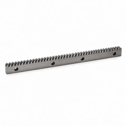



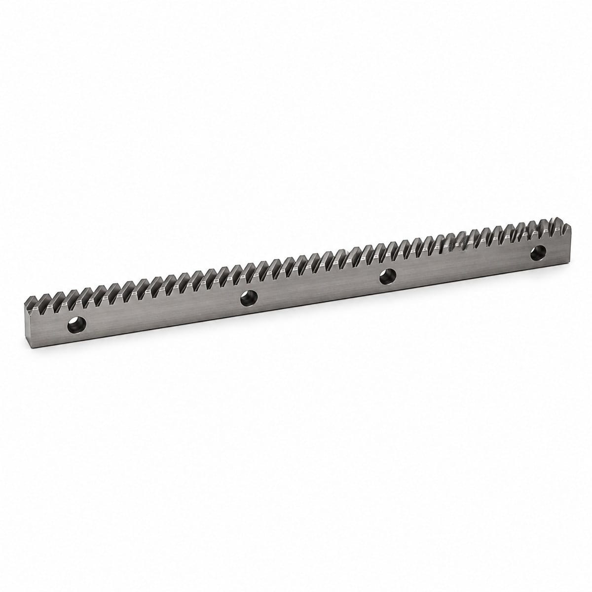

Helical Gear Rack for CNC Engraving Machines
Helical gear rack for CNC router and engraving machine axes. M1.25 to M3 module, 1000 to 2000 mm lengths, C45 steel at 20-25 HRC, 20 degree pressure angle and 19 degree 31 minute right-hand helix. DIN 8e27 standard, milled or ground flanks, made to drawing for non-standard axes.
Need a Quote?
For pricing, drawings, lead time and technical support, please contact our sales team.
- ✓ OEM & Custom Manufacturing
- ✓ Technical Drawing Support
- ✓ Fast Delivery
- ✓ Worldwide Shipping
Helical gear rack for CNC router and engraving machine linear axes, in M1.25 to M3 module and 1000, 1500 and 2000 mm lengths. C45 steel, 20° pressure angle, 19°31′42″ right-hand helix, DIN 8e27 (JIS grade 4) as standard. Milled or ground tooth flanks, and made to drawing for non-standard axes.
Why Engraving Axes Use Helical Racks
On an engraving or routing machine the tool path is the product, so anything that makes the axis move unevenly shows up in the finished part. A helical tooth enters mesh gradually along its width instead of across its whole face at once, which keeps the transmitted force more constant as each tooth engages.
The practical result is less cyclic variation at tooth-passing frequency — the effect that appears as fine periodic marking on a cut surface at exactly the spacing of the rack pitch. On a transport axis this would not matter. On a cutting axis it is visible in the work.
The cost of the helix is an axial force component that the pinion bearings have to absorb. On a machine designed for a helical rack this is accounted for. On a retrofit it is worth checking, because a bearing arrangement intended for a straight rack may not be located against thrust. Our comparison of straight and helical gear racks sets out that trade-off in full.
Standard Specification
| Item | Specification |
|---|---|
| Module | M1.25, M1.5, M2, M2.5, M3 |
| Length | 1000, 1500, 2000 mm |
| Tooth form | Helical, right-hand 19°31′42″ |
| Pressure angle | 20° |
| Material | C45 steel |
| Heat treatment | Quenched and tempered, 20–25 HRC |
| Accuracy grade | DIN 8e27 (JIS grade 4) |
| Tooth finish | Milled standard; ground on request |
| Jointing | Continuous linking, pitch carried across the joint |
Choosing the Module
Module selection on a router axis is governed by gantry mass and cutting load, not by travel length. A larger module gives a stronger tooth and a higher load rating, but it also means more travel per pinion revolution, which changes the gear reduction the drive needs to hold resolution.
In practice, lighter machines with small spindles use the smaller modules in this range, and heavy gantry machines cutting metal use the larger ones. If you are specifying from scratch, send the gantry mass, spindle power and the axis resolution you need at the tool, and we will confirm the module against your pinion and gearbox ratio rather than leaving it as a guess.
Milled or Ground Flanks
Both finishes are available in this range, and the choice affects positioning accuracy directly. Ground flanks roughly halve the pitch error compared with milled flanks over the same reference length.
Grinding is justified where the axis positions open-loop, where absolute accuracy has to hold at the far end of a long travel, or where two axes interpolate and rack error becomes contour error. It is not justified where the machine references to a datum every cycle, or where the guideways and gearbox backlash already contribute more error than the rack would. Our article on ground versus milled tooth surfaces gives the measured figures for both.
Long Axes and Section Joints
Router axes longer than the standard section lengths are built from linked sections, and the joint is normally the largest single error contributor on the axis — larger than the pitch error inside either section.
These racks are produced for continuous linking, with section ends prepared so tooth pitch carries across the joint instead of restarting at it. When ordering a multi-section axis, give us the total travel rather than a section count, so we can set the section breakdown and end preparation to suit the travel you actually need.
Made to Drawing
As a gear and rack manufacturer we produce to drawing alongside the standard range:
- Non-standard length. Cut to a travel that does not divide into standard sections, so the joint falls where you choose.
- Mounting holes. Diameter, spacing, counterbore and end offsets matched to an existing gantry or beam.
- Helix hand. Left-hand where the drive layout requires it, or matched to an installed pinion.
- Tighter accuracy. Pitch error to a stated figure where the axis justifies it.
- Higher hardness. Above the standard range, with grinding after treatment where profile has to stay within tolerance.
- Matched pinion. Rack and pinion produced together so the pair meets the same grade.
Replacement Work
If you are replacing a worn rack on an installed machine, the tooth form has to match the pinion you are keeping. Send us the pinion — or a measurement of tooth pitch, an estimate of helix hand and angle, and photographs of the mounting — and we will confirm the specification before quoting.
It is worth inspecting the pinion at the same time. A worn pinion running against a new rack transfers its own wear pattern into the new part, and the axis does not return to its original accuracy.
Information to Include with an Enquiry
- Module and helix hand, or a pinion sample and tooth-pitch measurement.
- Total axis travel and preferred section length.
- Gantry mass, spindle power and material being cut.
- Required positioning accuracy at the tool, and whether the axis is open-loop or has axis feedback.
- Mounting hole pattern, or the beam drawing.
- Whether ground flanks are required, or whether a stated tolerance is the requirement.
If you send the axis requirement rather than a part number, we will tell you which module and finish it needs — including when a milled rack will hold your tolerance and a ground one is not worth paying for.
| Brand | KDI |
|---|---|
| Model | KDI-ERH-CUSTOM |
| Product Type | Helical gear rack |

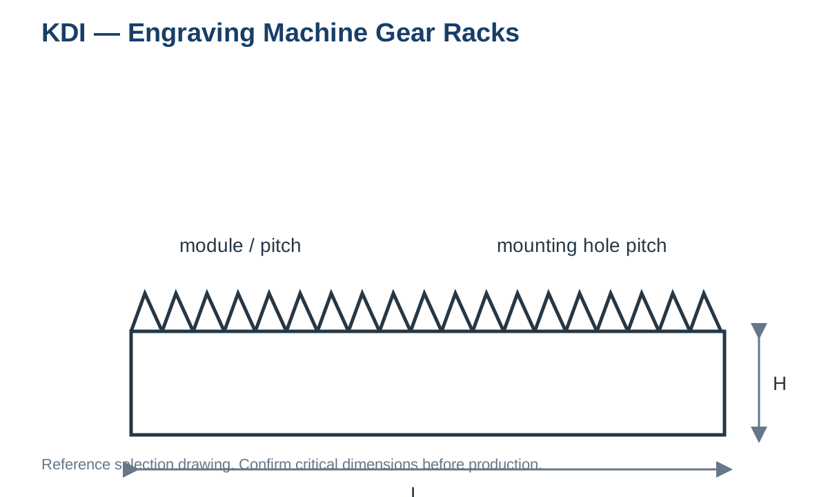
Engraving Machine Gear Racks — Reference Drawing
KDI-ERH-CUSTOM Specifications
| Module | M1.25 / M1.5 / M2 / M2.5 / M3 |
|---|---|
| Length | 1000 / 1500 / 2000 mm |
| Tooth form | Helical, right-hand 19 deg 31 min 42 sec |
| Pressure angle | 20 deg |
| Material | C45 steel |
| Hardness | Quenched and tempered, 20-25 HRC |
| Accuracy grade | DIN 8e27 (JIS grade 4) |
| Tooth finish | Milled standard, ground on request |
Engraving Machine Gear Racks Selection Table
| Model | Module | Length | Helix Angle | Material |
|---|---|---|---|---|
| ER-M1.25-1000 | M1.25 | 1000 mm | 19°31′42″ reference / custom | C45 steel |
| ER-M1.25-1500 | M1.25 | 1500 mm | 19°31′42″ reference / custom | C45 steel |
| ER-M1.25-2000 | M1.25 | 2000 mm | 19°31′42″ reference / custom | C45 steel |
| ER-M1.5-1000 | M1.5 | 1000 mm | 19°31′42″ reference / custom | C45 steel |
| ER-M1.5-1500 | M1.5 | 1500 mm | 19°31′42″ reference / custom | C45 steel |
| ER-M1.5-2000 | M1.5 | 2000 mm | 19°31′42″ reference / custom | C45 steel |
| ER-M2-1000 | M2 | 1000 mm | 19°31′42″ reference / custom | C45 steel |
| ER-M2-1500 | M2 | 1500 mm | 19°31′42″ reference / custom | C45 steel |
| ER-M2-2000 | M2 | 2000 mm | 19°31′42″ reference / custom | C45 steel |
| ER-M2.5-1000 | M2.5 | 1000 mm | 19°31′42″ reference / custom | C45 steel |
| ER-M2.5-1500 | M2.5 | 1500 mm | 19°31′42″ reference / custom | C45 steel |
| ER-M2.5-2000 | M2.5 | 2000 mm | 19°31′42″ reference / custom | C45 steel |
| ER-M3-1000 | M3 | 1000 mm | 19°31′42″ reference / custom | C45 steel |
| ER-M3-1500 | M3 | 1500 mm | 19°31′42″ reference / custom | C45 steel |
| ER-M3-2000 | M3 | 2000 mm | 19°31′42″ reference / custom | C45 steel |
Reference selection information for catalog use. Confirm critical dimensions, mating components, material, heat treatment and complete configuration before production or shipment.