



Blog
Ground vs Milled Gear Rack Teeth: What Pitch Error Costs You

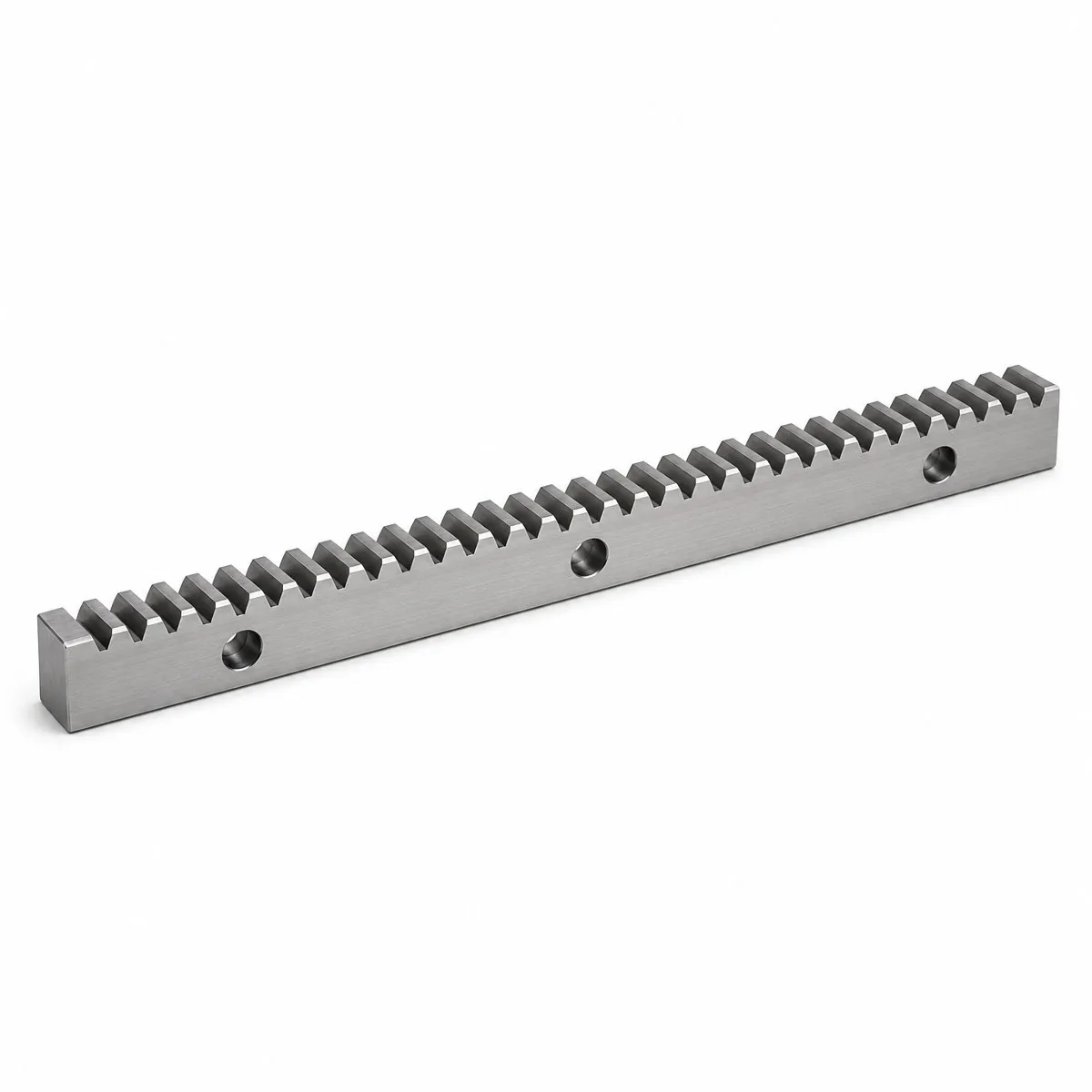
Two gear racks can carry the same module, the same material and the same hardness, and still differ by a factor of two in pitch accuracy. The variable is how the teeth were finished: milled or ground.
This matters because pitch error is the one rack characteristic a servo cannot correct. The drive knows where the motor shaft is, not where the tooth actually sits. Any deviation between the nominal tooth position and the real one lands directly on the workpiece.
The Two Finishing Routes
A milled rack is cut to final tooth form with a hob or a form cutter and leaves the machine ready to use. A ground rack goes through the same cutting stage, then returns for a grinding pass that removes a small envelope of material from the flanks and re-establishes the profile after heat treatment has moved it.
Grinding is not a polishing step. Its purpose is dimensional: it corrects the distortion that quenching introduces and it takes the accumulated pitch deviation down to a level that milling alone cannot reach on a hardened blank.
What Pitch Error Actually Measures
Pitch error is the difference between where a tooth should be and where it is, measured across a fixed reference length rather than between two neighbouring teeth. A rack can have visually uniform teeth and still drift, because each small deviation adds into the next.
That is why the figure is quoted over a reference length. A single tooth-to-tooth variation is usually harmless. The same variation repeating in the same direction across a reference length is what shows up as a dimensional error on the part being cut.
The Measured Difference
These are the pitch-error figures from our own gear rack catalogue, quoted on a 300 mm reference length, for straight racks with a 20° pressure angle:
| Module | Milled teeth | Ground teeth |
|---|---|---|
| M1 | 0.037 mm | — |
| M1.5 | 0.040 mm | — |
| M2 | 0.042 mm | 0.022 mm |
| M3 | 0.044 mm | 0.024 mm |
| M4 | 0.046 mm | 0.024 mm |
| M5 | — | 0.025 mm |
Across the overlapping range the ground racks sit at roughly half the pitch error of the milled equivalents. On the circular-pitch range the ground figures are similar, between 0.021 and 0.022 mm.
Two observations are worth drawing out. First, the milled figure grows with module — a larger tooth means a larger cutter, more cutting force and more deflection. Second, the ground figure stays nearly flat across modules, because grinding is a corrective operation referenced to a datum rather than a generating one.
How the Error Behaves Over a Long Axis
A common mistake is to multiply the per-300 mm figure by the number of 300 mm lengths in the axis. Pitch error is not strictly cumulative in that way; deviations partly cancel, and the real total depends on how the sections were produced and matched.
What does accumulate predictably is joint error. On a multi-section axis, the transition between one rack and the next is usually the largest single contributor — larger than the pitch error inside either section. If you are specifying a long travel, the joint tolerance and the matching method deserve at least as much attention as the accuracy grade.
When Milled Teeth Are the Right Choice
Milled racks are the correct engineering answer more often than buyers assume. They are appropriate where:
- The application positions to a hard stop, a proximity switch or a mechanical datum rather than by open-loop count.
- Repeatability matters more than absolute accuracy — returning to the same point reliably is largely unaffected by pitch error.
- The axis is a transport or feed move rather than a cutting move.
- The structure, guide rails or gearbox backlash already contribute more error than the rack would.
Specifying ground teeth on an axis whose guideway deflects by several hundredths under load buys nothing. The rack stops being the limiting component long before the tooth flanks do.
When Grinding Is Justified
- Open-loop or semi-closed-loop positioning where the control has no feedback from the axis itself.
- Long unsupported travels where absolute position at the far end has to hold a tolerance.
- Cutting, engraving or dispensing where the tool path is the product.
- Multi-axis interpolation, where error in one axis shows up as contour deviation rather than a simple offset.
- Any axis where the rack is genuinely the largest error source in the chain.
The Interaction with Heat Treatment
Hardening and accuracy are linked, and the order of operations decides the outcome. Our standard gear rack material is C45, quenched and tempered to 20–25 HRC. At that hardness teeth can be cut after treatment and the profile stays within the milled tolerance band.
Push the hardness higher and that stops being true. The blank moves during quenching, and the only way back to a tight profile is to grind afterwards. So a request for high surface hardness and tight pitch error is really a request for a grinding operation, whether or not the drawing says so. Our article on materials and heat treatment covers the hardness side of that decision.
Cost, Lead Time and What to Put on the Drawing
Grinding adds a machine operation, fixturing and inspection time. It is not a small percentage adder, and on long racks it can dominate the piece price. The honest comparison is against the cost of the accuracy actually being bought — if the machine cannot use it, it is spent for nothing.
To get a quote that reflects what you need, state the accuracy requirement as a number rather than a word. “High precision” is not specifiable. These are:
- Module and pressure angle, and whether teeth are straight or helical.
- Permitted pitch error and the reference length it applies to.
- Whether the flanks must be ground, or whether the tolerance is the requirement and the method is ours to choose.
- Required hardness and where it is measured.
- Total travel and how many sections it will be built from.
- Joint tolerance between sections, if the axis is multi-section.
The fourth point is worth stressing. Specifying a tolerance rather than a process lets the manufacturer pick the cheapest route that meets it. Specifying “ground” when a milled rack would have held your tolerance means paying for a process you did not need.
Frequently Asked Questions
Does a ground rack need a ground pinion?
Not always, but the pairing decides the result. A ground rack running against a coarse pinion will not deliver its rated accuracy at the tool. If the axis justifies a ground rack, the mating pinion normally deserves the same grade.
Can pitch error be corrected in the controller?
Partially, with a mapped compensation table and a feedback device that reads the axis rather than the motor. This works for repeatable, stable error. It does not correct random variation, and it adds a calibration step to every build.
Is a ground rack more wear-resistant?
Grinding improves the contact pattern, which spreads load over more of the flank and can reduce local stress. But wear resistance is governed mainly by material, hardness and lubrication. Grinding a soft rack does not make it last longer.
How do I tell which finish an existing rack has?
Ground flanks show a fine, directional finish running across the tooth; milled flanks show the scallop pattern of the cutter. Under magnification the difference is obvious. Surface appearance alone does not confirm the pitch grade — that requires measurement.
Final Review Checklist
- Identify the largest error source in the axis before specifying the rack.
- State pitch error as a number with its reference length.
- Check whether your positioning method is open-loop or referenced to a datum.
- Match the pinion grade to the rack grade.
- Treat section joints as a separate, explicit tolerance on long axes.
- Confirm that required hardness and required accuracy are compatible in one process route.
We manufacture gear racks in both finishes, in straight and helical form, to DIN 8e27 (JIS grade 4) as standard. If you send the axis requirement rather than a part number, we will tell you which finish it actually needs — including when the answer is the cheaper one.


